PPC (Power Plant Controller) is an interactive SCADA (monitoring) system that includes related control algorithms, works with Solarify monitoring platform and data logger, and has its own separate and fast control mechanism.
Annex-18 article is the annex of the Electricity Network Regulation that defines the grid connection criteria of photovoltaic generation facilities based on wind and solar energy. Solarify PPC was developed as a solution that controls and manages solar energy systems to meet the criteria requested in Annex-18.
In accordance with EPDK/TEİAŞ, Annex-18 article in the Electricity Network Regulation has become extremely important. Within the scope of this article, with the Solarify data logger;
- Contribution of Production Plants to the System after Fault,
- Active Power Control,
- Frequency Response,
- Reactive Power Capacity,
- Providing Reactive Power Support
becomes applicable.
Let's take a brief look at these items determined by the regulation.
1) Contribution of Production Plants to the Post-Fault System
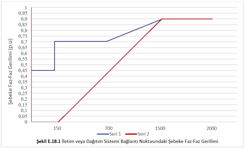
During the period that the mains phase-to-phase voltage at the transmission or distribution system connection point remains in zones 1 and 2 given in Figure E.18.1, the relevant generation facilities must remain connected to the mains in case of voltage drops occurring in any or all phases.
2) Active Power Control
This control is used to keep the total power of the plant at a determined value. Thus, by entering the highest and lowest set values of the plant, it can be prevented from exceeding the installed power. With the active power feature, it will be determined in which power range the plant will produce, and it will be prevented from exceeding the installed power value, thus preventing the plant from penalizing.
Active power control can be done in case of emergency defined in article 63 of the regulation in photovoltaic generation facilities based on wind and solar energy connected to the transmission system.
The active power output of the generation facility should be automatically controlled between 20%-100% of the power available to the power plant under current conditions, with signals to be sent by TEIAS when necessary. In this context;
a) For generation facilities with an installed power of 100 MW or less, the load-taking rate should not exceed 5% of the installed power of the power plant per minute, and the load-shedding rate should not be less than 5% of the installed power of the power plant per minute.
b) For generation facilities with an installed power of more than 100 MW, the load-taking rate should not exceed 4% of the installed power of the plant per minute, and the load-shedding rate should not be less than 4% of the installed power of the plant per minute.
3) Frequency Response
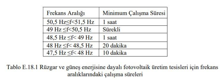
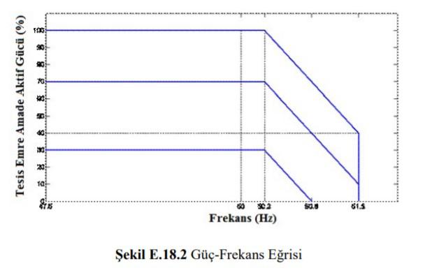
Photovoltaic generation facilities based on solar energy should produce during their operation, based on the frequency ranges in Figure E.18.2 below. During the design and operation of the power plants, the operating times in the frequency operating ranges in Table E.18.1 given below will be taken as the basis.
In addition to these operating conditions, additional wind turbine and/or solar panel group should not be activated when the grid frequency is above 50.2 Hz in the relevant production facility. The total active output power of the production facility must be within the limits of the power-frequency curve given in Figure E.18.2.
4) Reactive Power Capacity
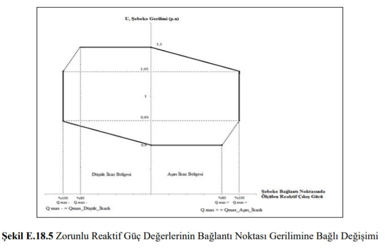
These mandatory reactive power values, which are determined and recorded with ancillary service agreements, should be reached when necessary, depending on the voltage, as indicated in Figure E.18.5.
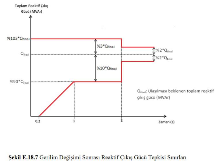
5) Providing Reactive Power Support
For generation plants connected to the transmission system, the voltage set value will be given by TEIAS for the grid connection point voltage. Generation facilities should respond proportionally to changes in grid connection point voltage as seen in Figure E.18.6.
The voltage drop (droop) value in the chart is between 2% and 7% and is determined by TEIAS. Related production facility;
- must be at transmission grid connection contact voltage,
- as indicated in the graph in Figure E.18.7, should start to respond in 200 ms at the latest,
- The reactive output power should reach 90% of the balance value within 1 second at the latest and it should stabilize within 2 seconds at the latest.
- In equilibrium, the peak value of the oscillations that may occur in the reactive output power should not exceed 2% of the actual change.
For more information: info@loggma.com.tr